Abstract
In this article, we introduce adaptive optics and focus on the advantages of using (short-wave) infrared cameras in wavefront sensing. We also highlight some key applications in astronomy, laser communication, biological imaging microscopy and retinal imaging in combination with optical coherence tomography. We conclude with the key performance parameters of SWIR cameras used in adaptive optics applications
Introduction
In 1953, H. W. Babcock wrote “The possibility of compensating astronomical seeing” in the “Publications of the Astronomical Society of the Pacific” [pha], [str]. He discussed the severe limitations imposed on astronomical observations caused by the turbulent atmosphere of the earth and proposed ‘adaptive optics’ (AO) as a concept to improve astronomical imaging. The concept involved correcting for wavefront errors caused by the variations of the index of refraction in the atmosphere. Although his suggestions were of significant interest for the U.S. military, it took about two decades for technology to catch up with theory and the first AO system to be mounted on a telescope. The fast technological advances in cameras and deformable mirrors have also led to the introduction of adaptive optics in other application fields such as microscopy, retinal imaging and laser communication [Boston].
What is adaptive optics?
Adaptive optics (AO) is a technique to measure the wavefront errors or distortions, and to correct the resulting image in real time. A typical AO systems consists of three main components:
- Wavefront sensor (WFS) – to measure the errors or distortion
- Control system – to calculate the required correction and drive the corrector
- Wavefront corrector – to apply the compensation for the distortion
The most common WFS is called a Shack-Hartmann Wavefront Sensor (SH-WFS). This simple instrument was first used in 1971 by the NASA and in military programs, and it relies on the basic principle of light, i.e., light waves travel in a straight line in homogeneous media and the wavefront is the surface perpendicular to the local direction of propagation [Neal]. The WFS splits light in a number of small beams (subapertures) using a lenslet array [pha]. The light spots are then focused on a two-dimensional imager or camera. As the wavefront is distorted, the focused spots move, characterizing the wavefront.
The control system is typically a computer running a control algorithm software. The goal is to determine the positions of the focused spots, to compute the wavefront slope and to calculate the reconstruction of the wavefront by integration, and finally to send this information to the wavefront corrector.
The most prevalent technology used as wavefront corrector is a deformable mirror (DM). Many different versions and types of DM’s exist and the selection criteria are application driven. The number of actuators can vary from less than 20, to more than 4000 actuators for a MEMS (MicroElectro Mechanical System) DM used for extreme AO in astronomy.
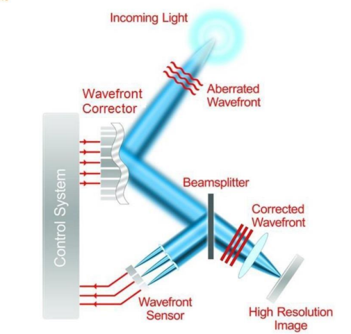
Fig. 1: Traditional adaptive optics components and configuration. Adapted from C. Max, Center for Adaptive Optics [Boston]
AO in astronomy and advantages of using infrared in wavefront sensing
The very dynamic atmospheric turbulence causes random spatial and temporal wavefront distortions, severely limiting the ability to capture high resolution and precise images of stars and exoplanets. For AO in astronomy, we have to make a clear distinction between the camera used in the WFS, and the camera used for observation.
The use of AO in astronomy critically depends on the ability to provide a reference measurement of the wavefronts distorted by the atmosphere. Wavefront sensing is therefore done on a reference star, called a natural guide star, if such a star can be found in close proximity to the object that one wants to observe. In some cases, the object itself can also be used if it is bright enough and if it has sharp light gradients. The wavefront sensing measurement can be performed in the visible for observation in infrared, or in the infrared itself, in case the reference star is not bright enough in visible [ESO].
Current AO systems based on visible sensors are severely limited in sky coverage [Kenworthy]. By going to low noise short-wave infrared (or even better visible-enhanced SWIR) cameras, one can access fainter guide stars, and the star density in the infrared band (J, H, K) is higher than in the visible [Rigaut]. In other words, it is easier to find natural guide stars in the infrared. The higher surface density of “late type” stars with more infrared flux enables us to significantly increase the sky coverage [Brandl]. Also self-referencing red objects too faint in the visible can be used for wavefront sensing.
Wavefront calculation has to be done fast (typically within 1 ms) otherwise the state of the atmosphere may have changed. This necessitates the use of fast and sensitive cameras in wavefront sensing. A short exposure time has to be used to “freeze” the effect of atmospheric turbulence. A high frame rate and low latency has to be used to send the correction info to the DM, in order to correct the wavefronts in real time. Moreover, relatively bright guide stars and high sensitivity detectors are needed to guarantee a high enough signal to noise ratio on the WFS.

Fig.2: Observation in H-band (1500 nm) of star Fomalhaut with Cougar SWIR camera as scientific imaging camera. Picture left uncorrected, picture right corrected with AO. (Credit: Dr. Ren Deqing from California State University Northridge)
AO in biological microscopy
In vivo imaging is critical in biological microscopy – living tissue is much more relevant for studying cellular processes. The limiting factor in this application however, is the amount of light that can be used without damaging the tissue [Boston]. AO can be used to correct wavefront errors introduced by scattering in tissue. A combination of SWIR wavelengths and AO would be ideal for deep-tissue in vivo imaging, and to extract vital information from biological specimens.
AO in retinal imaging
Retinal imaging is used to detect an eye disease before its onset, and to start early treatment. Eye pathologies include glaucoma, diabetic retinopathy and age related macular degeneration. Moreover, leading scientists believe that the ability to resolve individual retinal cells (~ 3 μm) and ocular blood flow through microscopic vasculature will allow them to monitor changes in a patient’s health. The human retina is a window to the heart, and researchers have shown that there is a link from retinal vasculature damage to coronary heart disease, stroke and diabetes.
At the moment, ultra-high resolution images of the human retina are not yet possible due to imperfections of the eye itself (cornea and lens), causing wavefront distortions. There are two main techniques using AO for eye imaging: confocal scanning laser ophthalmology and optical coherence tomography [Boston]. For both techniques, AO can significantly improve the resolution. In the case of OCT, typically superluminescent diodes with a center wavelength around 840 nm are used [Yu]. However, the use of 1300 nm light, in combination with a SWIR camera, will allow for better penetration depths and less scattering in human tissue, and hence, substantially improve signal to noise ratios in the resulting images.
Long range laser communication
For earth observation satellites, the increasing resolution of imaging sensors requires much higher data rates for the data downlink than what is currently feasible with conventional RF (radiofrequency) technology [Giggenbach]. Free-space laser communication is a promising technique for transmission of data without the need for wires or optical fibers. However, when sending data over long distances (> 1 km), atmospheric turbulence will limit the achievable data rate. The optical signal wavefront will be distorted by variations of the index of refraction due to atmospheric turbulence, and also clouds can cause fading or link blockages. AO can correct the wavefronts of the laser pulses and in this way, increase the achievable data rate and improve the bit-error-rate (BER).
Especially for “near-earth flight terminals” (aircraft downlinks), eye-safety in wavelength selection is a critical issue for the ground station operators. The use of free-space lasers at 1550 nm has the advantage of being about 100x more eye-safe than wavelengths around 800 nm. This allows the use of larger laser powers. Moreover, at 1550 nm, the system will also suffer less from background light from celestial bodies, clouds and earth albedo. Hence, blinding of tracking sensors will be reduced, and sensors with a wider field-of-view can be used. Also, atmospheric attenuation is very low at 1550 nm. All this plays in favour of using 1550 nm lasers in combination with a high speed SWIR camera for wavefront sensing.
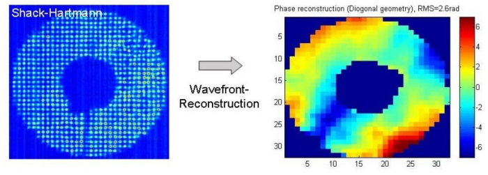
Fig. 3: Typical image of InGaAs wavefront sensor (Cheetah CL) with the reconstructed phase for a 400m link between two buildings [Giggenbach].
In addition to the use of adaptive optics in free-space laser communication, Shack-Hartmann wavefront sensors also find application in metrology and characterization of laser beams, LEDs and optical systems.
Camera selection
Xenics offers various types of SWIR camera in four wavelength ranges [Xenics]:
- 500 to 1700 nm (visible-enhanced InGaAs)
- 900 to 1700 nm (standard InGaAs)
- 900 to 2350 nm (T2SL)
- 900 to 2500 nm (T2SL)
When selecting a SWIR camera for wavefront sensing, the following performance parameters are key:
- A high speed, high frame rate camera with low latency has to be used because the camera will be used in a WFS in the control loop for correction in real time. Xenics offers a wide range of high speed SWIR cameras. The Xenics Cheetah camera is the world’s fastest SWIR camera with a maximum frame rate of 1730 fps for a 640×512 resolution in the 500 to 1700 nm or 900 to 1700 nm band.
- A short exposure time (< 1 ms) will be necessary for most applications in order to “freeze” the state of the transmission medium. All Xenics SWIR cameras allow flexible use of exposure time setting.
- A low (read) noise sensor will allow for better signal to noise rations. The images will be read noise limited as the exposure times for WFS will always be short and shot noise generated by dark current will not play a dominant role.
- In some applications (astronomy), a visible enhanced SWIR camera will be advantageous as it will be sensitive in a broader wavelength band.
- A high resolution sensor will allow for accurate measurement of spatial wavefront distortion. Xenics high speed cameras come in either 320×256 or 640×512. Flexible window of interest settings are available on most cameras in order to capture images at even higher frame rates.
- All Xenics SWIR cameras come without Stirling cooler, and without cold stop. Stirling coolers can cause vibrations, and not having an internal cold stop is also an advantage when using a SWIR camera in a WFS: an aperture smaller than the detector size complicates the use for wavefront sensing.
Conclusion
In this article, we have discussed the basic working principle of AO in astronomy, microscopy, retinal imaging and laser communication application. We have highlighted the benefits of using SWIR cameras for WFS in each of these applications. We have summarized the key performance parameters of SWIR cameras in AO applications and introduced the Xenics range of high speed SWIR cameras.
References
[Rigaut] Astronomy and astrophysics – Letter to the editor: “Visible and infrared wavefront sensing for astronomical adaptive optics”, F. Rigaut, et al., Observatoire de Paris et Université Paris VII, France; March 1991.
[Boston] Boston Micromachine Corporation Shaping Light – Adaptive Optics 101 Technical White Paper
[Brandl] “An infrared optimized AO system for a 15 – 20 m class telescope”, B. R. Brandl, et al., Center for Radiophysics and Space Research, Cornell University, Ithaca, NY, USA.
[Neal] “Characterization of infrared laser systems”, D. R. Neal, et al., WaveFront Sciences, Inc., 15100 Central S.E., Albuquerque, NM, USA. Part of SPIE Conference on Infrared Spaceborne Remote Sensing VI, San Diego, CA, USA – July 1998.
[Giggenbach] “Optical data downlinks from earth observation platforms”, D. Giggenbach, et al., Institute of Communications and Navigation, German Aerospace Center (DLR), D – 82234 Wessling, Germany. Proc. of SPIE 7199, 2009.
[ESO] “What is active and adaptive optics?”, www.eso.org/sci/facilities/develop/ao/what_ao/html
[pha] “Adaptive optics”, www.pha.jhu.edu/~jlotz/aoptics/node4.html
[str] “A new view of the universe”, https://str.llnl.gov/str/Olivier.html
[Yu] “High-speed adaptive optics for imaging of the living human eye”, Y. Yu, et al., Department of Ophthalmology, University of Alabama at Birmingham, AL, USA. Optics Express 23035 – 7 Sep 2015.
[Kenworthy] “A visible/infrared low noise, fast readout wavefront sensor for all-sky adaptive optics”, M. A. Kenworthy, et al., Steward Observatory, Tucson, AZ, USA. Proc. of SPIE Vol. 6276 62760V-1.
[Xenics] www.xenics.com
Documentation
Application Note


Related content

Munich.
FROM Nov 10th 2026 TO Nov 13th 2026
SEMICON EUROPA 2026
Join Exosens at SEMICON EUROPA 2026 2026 in Munich

Edinburgh.
FROM Sep 14th 2026 TO Sep 17th 2026
SPIE Sensors + Imaging 2026
Join Exosens at SPIE Sensors + Imaging 2026 Edinburgh, United Kingdom

Jul 07th 2026
Multifocal Femtosecond Laser Writing
Crosstalk Limits in Multifocal Parallel Femtosecond Direct Laser Writing: Decoherence Strategies and Quantitative Validation of Nanostructure Optical Phase

Jun 29th 2026
Exosens secures contract with BROLIS
Exosens secures major long-term contract with BROLIS to supply 17000 high-performance image intensifier tubes for the Czech Armed Forces

Aug 20th 2021
Visit our booth #514 during OPTIFAB

Jun 25th 2026
Strengthening Defense & Security Innovation
Exosens secures €140 million in EIB financing to foster innovation in Europe’s defense and security industry